BIM Models
View and explore IFC, Navisworks, and Revit building models in Lunr's browser-based 3D viewer, with tools for navigation, measurement, sectioning, model inspection, clash detection, and scene management.
Overview
Lunr's browser-based 3D viewer opens building models in 3D directly in your browser, so there is no desktop software to install. It reads IFC, Navisworks, and Revit files.
The first time a model is opened it is processed for viewing, and you may see it downloading and processing before it appears. The processed model is then cached, so opening it again is fast.
Models open in your browser with no plugin or download required.
Opening a Model
Open an IFC, Navisworks, or Revit document from the repository in the same way as any other document, and it opens in the 3D viewer.
While the model is being prepared, you may see Downloading IFC..., Processing IFC file... and Rendering model... before the model appears.
Navisworks and Revit models are converted to a form the viewer can read before they can be opened, which your organisation must have enabled. Very large files are not converted, so a model above your organisation's size limit stays unavailable in the viewer.
Regenerating a Model
Where the prepared model is missing or out of date, select Regenerate model at the bottom right of the viewer to build it again. The button reads "Processing..." while it runs, and is unavailable while a regeneration is already in progress.
Scene Drawing Settings
Open Settings to change how the scene is drawn. From here you can enable shadows with Shadow visible, show a grid and choose the Grid level, and enable Ghost Mode to make the model transparent.
Opening Several Models Together
A Scene is a collection of 3D documents that open together as toggleable layers in one view, letting you read several models against each other rather than one at a time. Create and convert scenes from the Collections page, covered in Scenes. With more than one model loaded, the viewer also reports where their geometry overlaps, covered in Clash Detection.
Viewer Overview
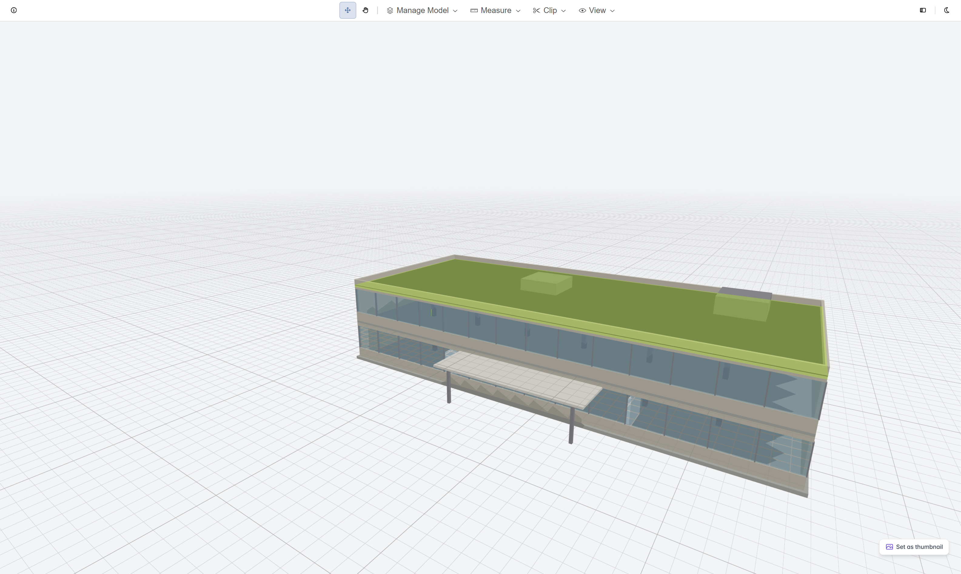
The viewer fills the browser window, with a toolbar across the top and panels that open down the sides.
Toolbar
The toolbar holds a help button, the camera controls, and the tool ribbons.
- The Orbit and Pan controls set how the mouse moves the camera.
- The Manage Model, Measure, Clip, and View buttons open ribbons of related tools.
- On the right are Settings and a light and dark scene toggle.
Press and hold the right mouse button to pan the camera at any time.
Navigation
Use Orbit to rotate around the model and Pan to move around the scene.
Open the View ribbon to jump to a preset view or change the camera.
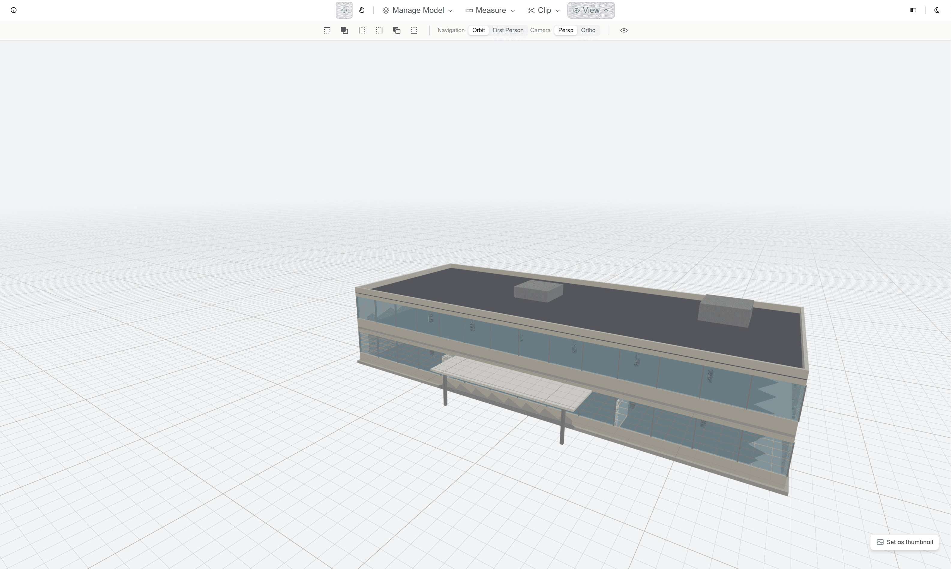
- Choose a preset view: Top view, Front view, Left view, Right view, Back view, or Bottom view.
- Switch Navigation between Orbit and First Person.
- Switch the Camera between the perspective (Persp) and orthographic (Ortho) projections.
Measurements
Open the Measure ribbon to measure the model. You can measure Length, Area, Volume, and Angle.
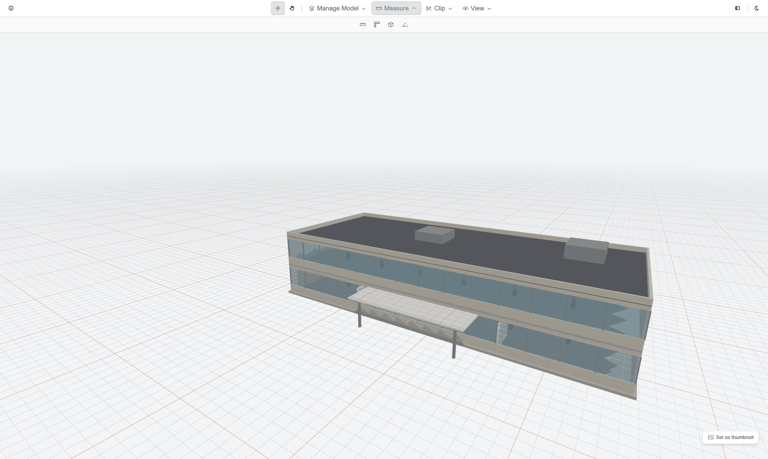
Pick a tool from the ribbon, then double-click the model to place a measurement. Each tool shows a short hint at the pointer while it is active. Lengths are reported in metres, areas in square metres (m²), volumes in cubic metres (m³), and angles in degrees.
Each tool has a Measurement visible toggle to show or hide its measurements, and a Delete All button to clear them.
Length
The Length tool measures the straight-line distance between two points on the model.
Double-click a first point, then double-click a second point. The distance is drawn between them and labelled in metres.
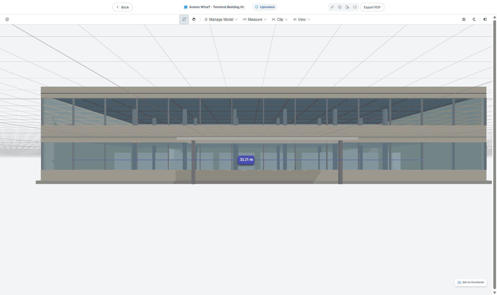
The tool can also show the dimension broken into its parts:
- Turn on Display Rectangle Dimensions to add the horizontal and vertical components of the measurement, and Invert Rectangle Dimensions to flip which way they are drawn.
- Turn on Display Projection Dimensions to add the measurement's projection onto the axes.
- Use Clear Complementary Dimensions to remove these extra dimensions and leave only the main length.
Area
The Area tool measures a rectangular area on a surface.
Double-click one corner of the region, then double-click the opposite corner. The rectangle between them is drawn on the surface and its area is reported.
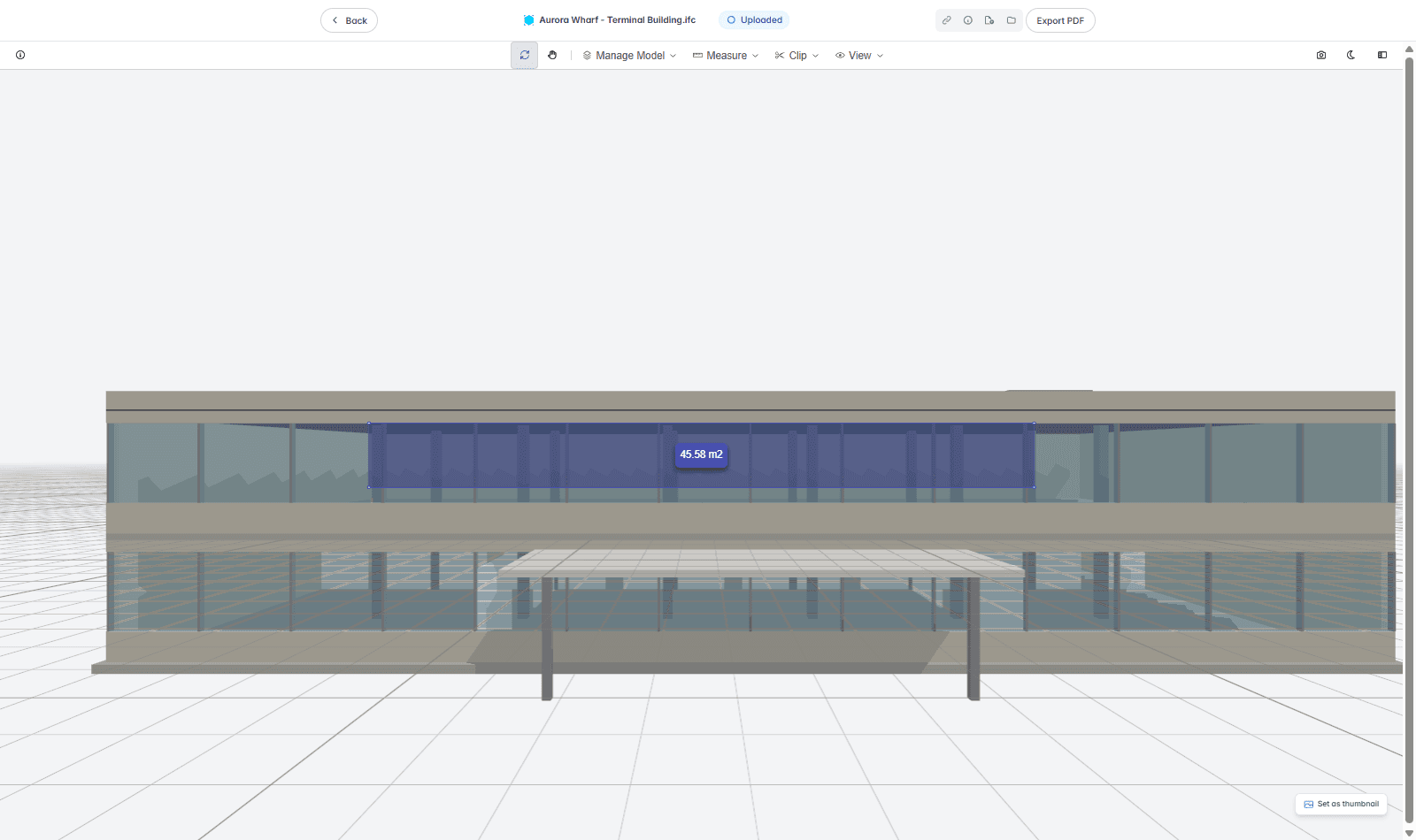
Use it for floor areas, wall faces, or any flat region you need to size.
Volume
The Volume tool reports the volume of model elements.
Double-click an element to select it and read its volume in cubic metres. The tool uses the element's own geometry, so you get the true volume of the object rather than a drawn box.
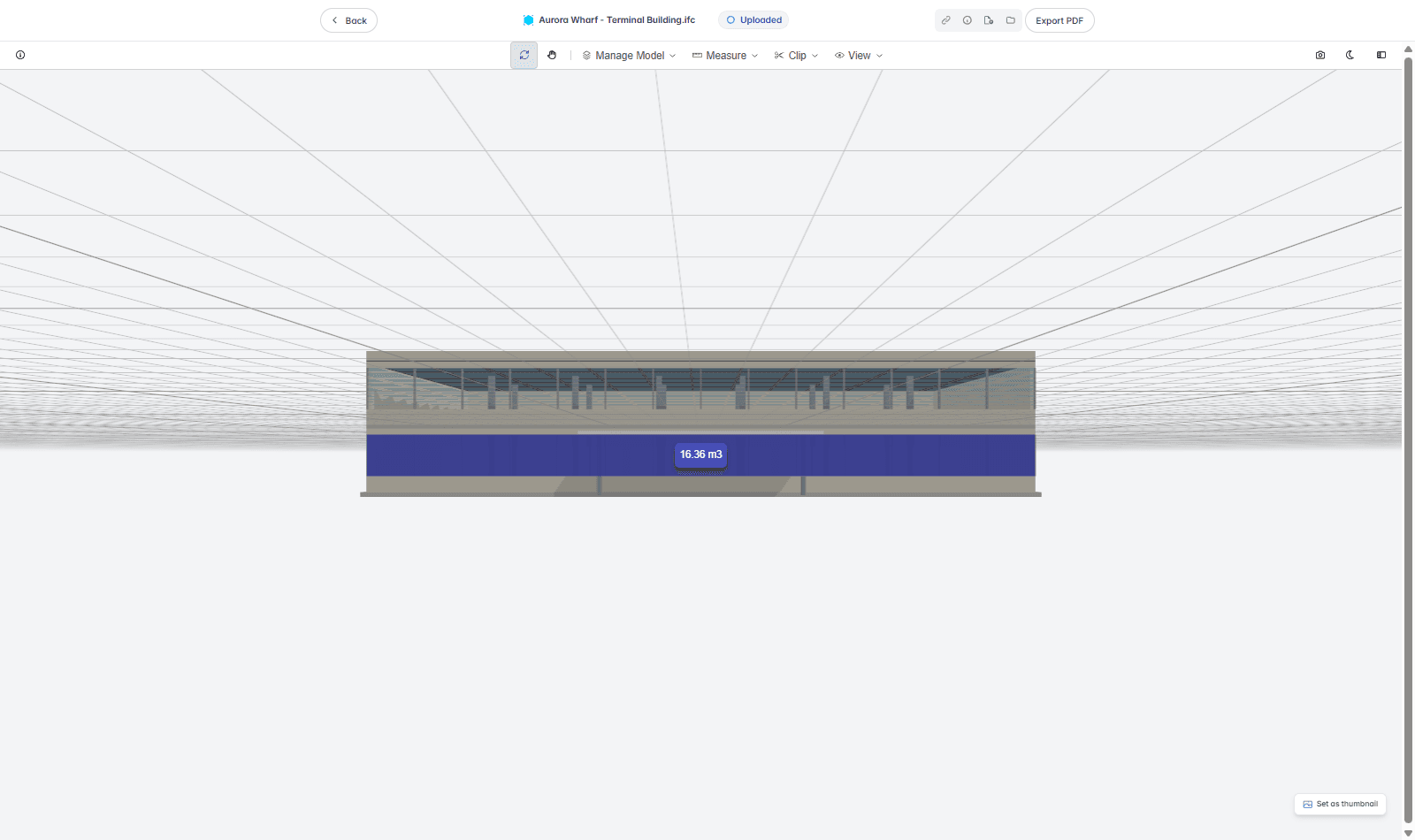
Use it to size structural members, slabs, or other components.
Angle
The Angle tool measures the angle formed by three points.
Double-click three points: the corner point is the middle one, and the angle is measured between the two arms. The angle is reported at the vertex.
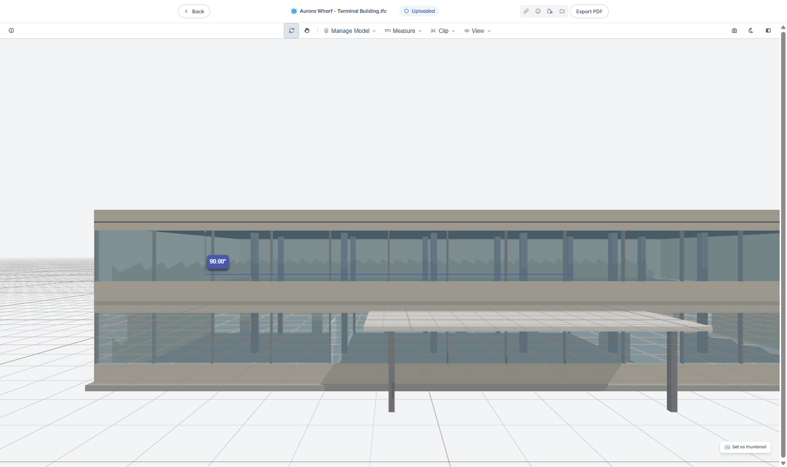
Use the Unit control to switch the reading between degrees and radians.
Sectioning the Model
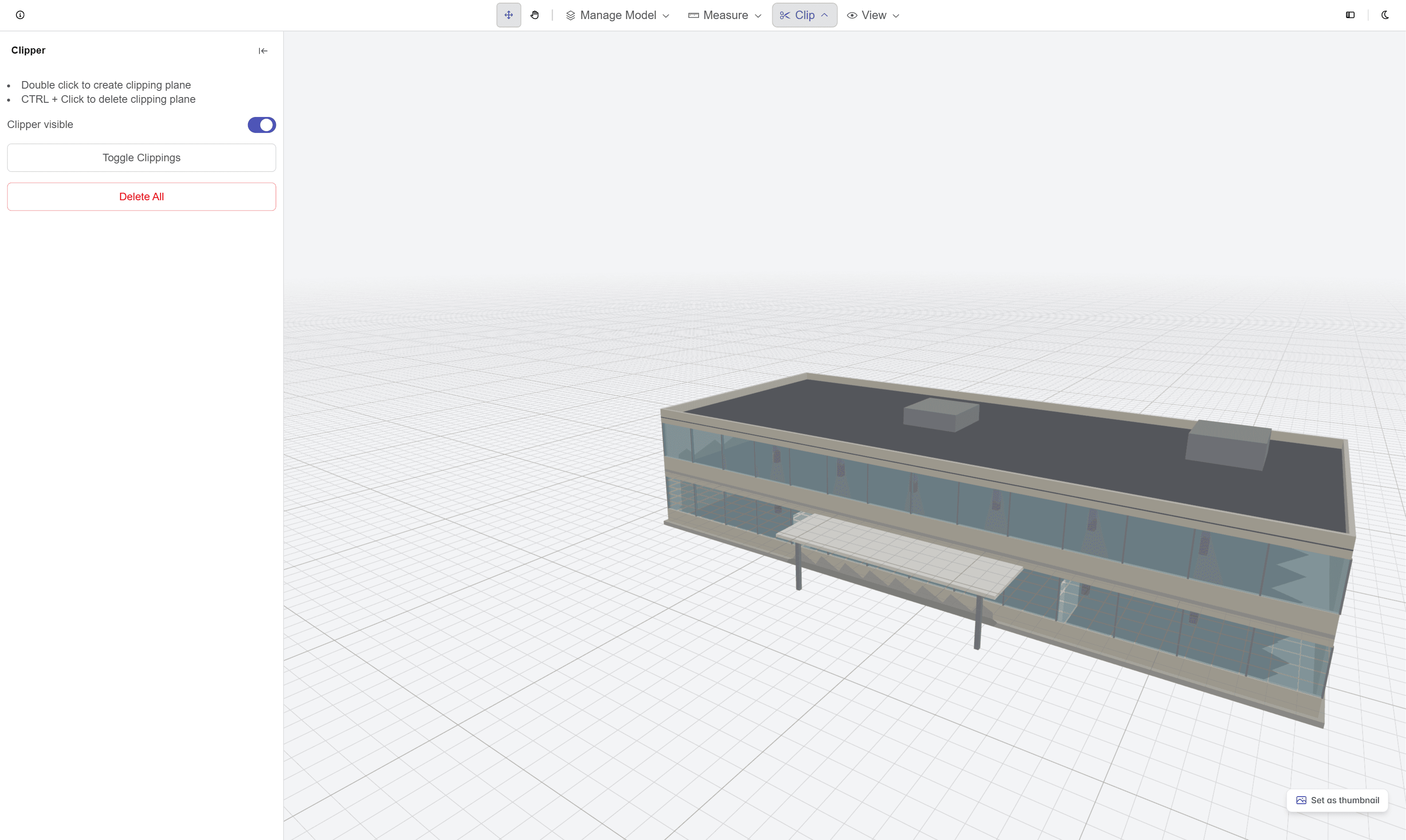
Open the Clip tool to cut through the model with a clipping plane. Double-click on a surface to create a clipping plane, hold Ctrl and click a plane to delete it, or use Delete All to remove them.
Working With the Model
Open the Manage Model ribbon to work with the model's contents:
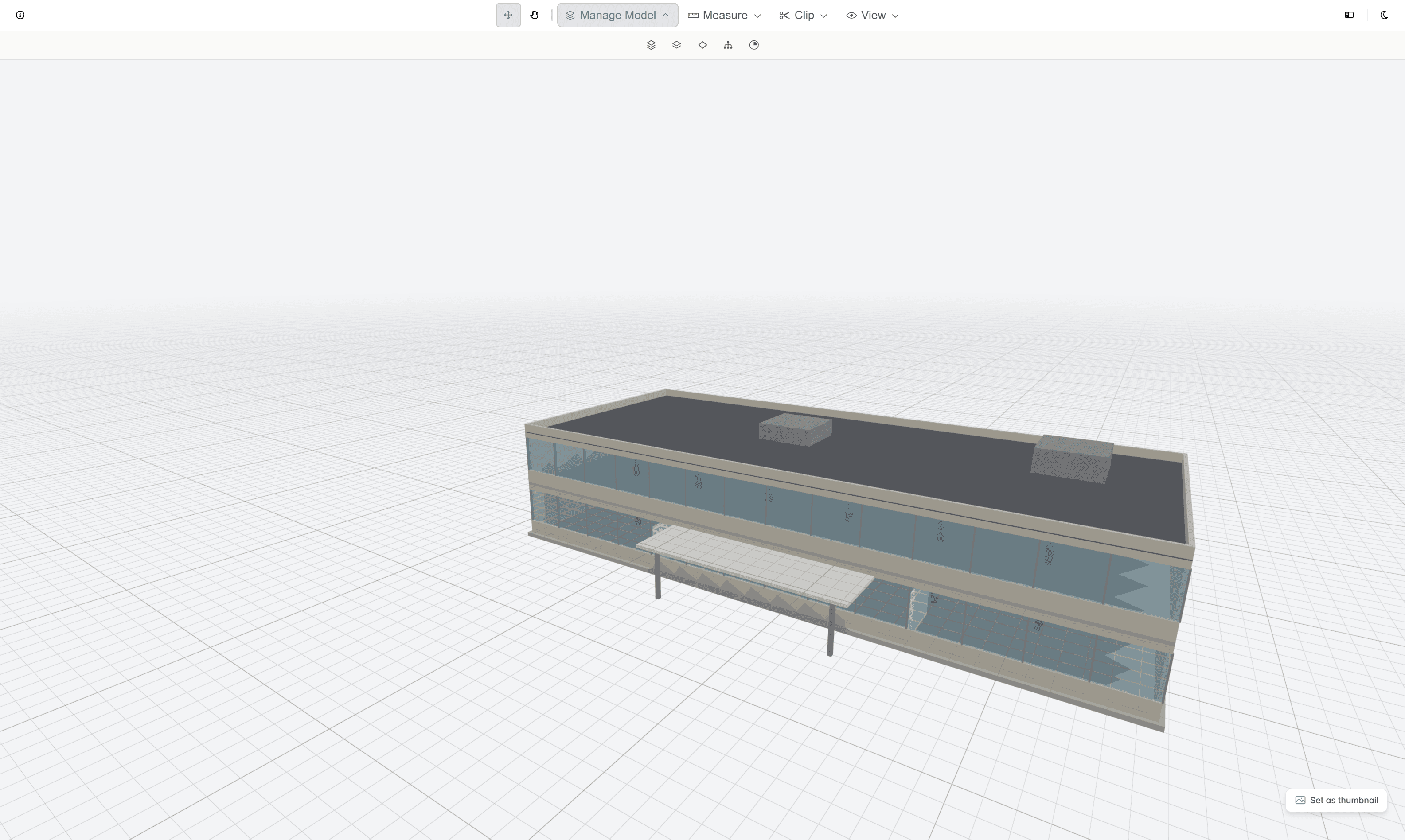
- Models lists the loaded BIM models.
- Model Inspector and Item Inspector let you explore the model tree and elements. Click a model item to highlight or inspect it, and hold Ctrl and click to add more items to the selection.
- Classifier groups elements by category, so you can Isolate Category or Hide Category, and Reset Visibility to bring everything back.
- Model Attributes displays the model's attributes as a chart. Click a chart section to highlight the matching elements in the 3D view.
Right-click an element to Isolate or Hide it, or choose Show all objects to bring everything back.
Clash Detection
Where more than one model is loaded, the viewer checks whether those models collide. Clash detection compares every pair of loaded models and reports the places their geometry overlaps. Getting more than one model into the viewer at once means opening a scene, covered in Scenes.
Select the clash icon in the panel rail down the left of the viewer to open the Clash Detection panel. Select the cross at the top of the panel to close it again.
Running a Check
The check runs on its own as soon as the scene has two or more models loaded. There is nothing to start and nothing to configure.
While it runs, the panel reports its progress as "Checking model pairs..." followed by a percentage. Larger models take longer, and a model that finishes loading part way through is picked up by the next pass.
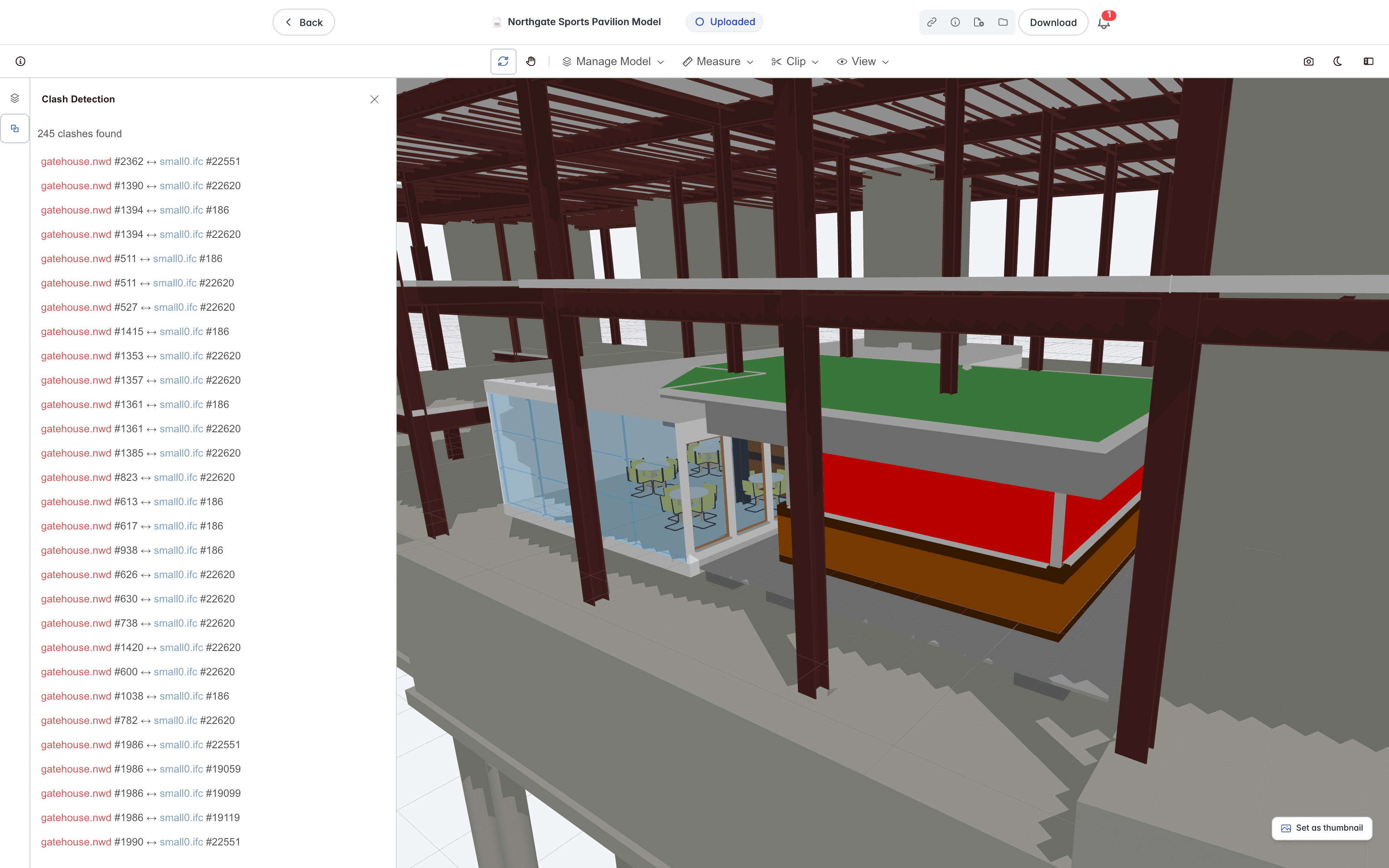
When the check finishes, the panel reports how many clashes it found, above the list of results. A scene with only one model in it reads "Load at least two models to detect clashes." instead, because there is nothing to compare.
Reading the Results
Each clash is one row, naming both sides: the first model and the element number inside it, then the second model and its element number. The two model names are coloured, red for the first and blue for the second, and those are the same colours the elements take in the viewer. Every pair of models in the scene is compared, so a scene of three models can report clashes between any two of them.
Select a row to see the clash. The element from the first model turns red, the element from the second turns blue, the region where they overlap is washed in purple, and the camera moves to frame the pair. The row stays marked in the list, so you can see where you are as you work down it.
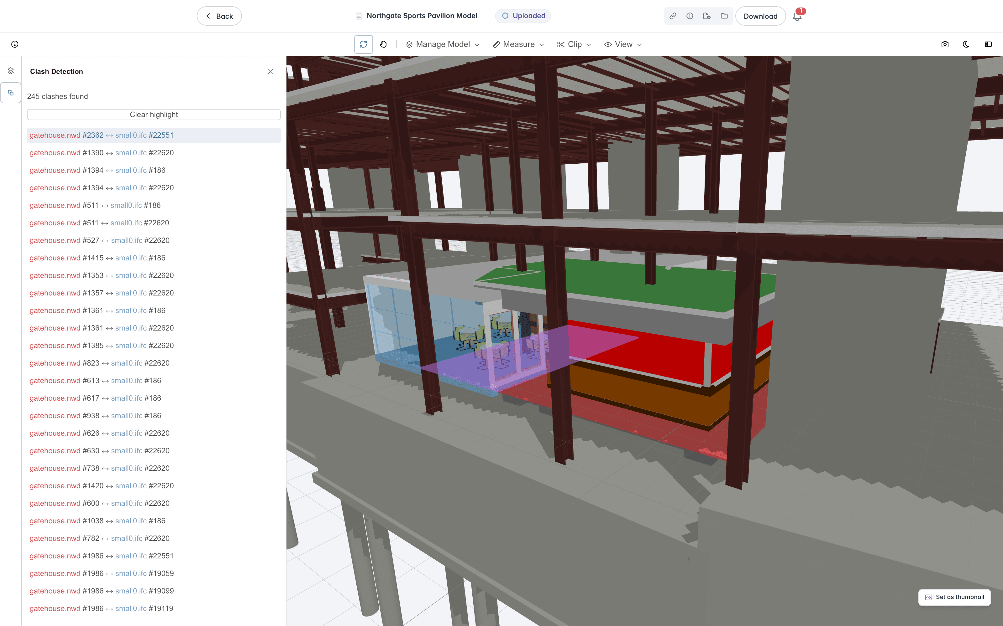
Select Clear highlight, which appears above the list once a row is selected, to take the colouring off the model and leave the results in place.
What the Results Do Not Do
Results are not saved with the scene. They belong to the viewing session, so closing the viewer discards them and opening the scene again runs the check afresh.
Inspecting Properties
Select an element to see its properties. You can read the values in the Item Properties table and use Copy as TSV to copy them out, ready to paste into a spreadsheet.
2D Views
Open the 2D Views panel to work with named 2D views. You can Open a view, Remove one, or use Close active 2D View.
Setting the Document Thumbnail
Frame the view you want, then click Set as thumbnail to capture the current view as the document's thumbnail. This requires the Manage Projects access right.
Excel Spreadsheets
View and navigate Excel workbooks in Lunr's browser-based spreadsheet viewer, with support for worksheet navigation, filtering, searching, exporting, and printing while preserving the workbook's original formatting.
Point Clouds
View and analyse LAS and LAZ point clouds in Lunr's browser-based point cloud viewer, with tools for navigation, measurement, clipping, visualisation, saved viewpoints, and scene management.