Viewing CAD Models and Assemblies
View Inventor and SolidWorks parts and assemblies, STEP mechanical parts, and STL meshes in Lunr's browser-based 3D viewer, with tools for measurement, sectioning, saved views, assembly parts, bills of materials, issues, model states, and revision comparison.
Overview
Lunr's browser-based 3D viewer opens mechanical CAD models directly in your browser, so there is no desktop software to install. It reads Inventor (.ipt parts and .iam assemblies) and SolidWorks (.sldprt parts and .sldasm assemblies) files, STEP (.step, .stp) mechanical parts, and STL (.stl) mesh files.
It is the same viewer used for building models, so the toolbar, scene settings, and keyboard shortcuts work as described in Viewing BIM Models. This page covers what is specific to CAD models and assemblies.
Opening a CAD Model
To view an Inventor model, a SolidWorks model, or a STEP model, open the document from the repository in the same way as any other document, and it opens in the 3D viewer.
Inventor and SolidWorks parts and assemblies, and STEP models, are prepared for viewing after they are uploaded. An assembly uploaded with Upload Assembly has its model built as part of the upload, covered in Uploading Assemblies. If the model has not been generated yet, or could not be generated, a Model not ready message appears. A STEP model that has not been prepared, and is not part of a scene, opens in a separate 3D viewer instead.
STEP models also list their product tree in a read-only Parts panel, which appears only when the model has more than one occurrence. It has no Status or Document column and no Open button.
STL files open the same way, with the mechanical tools described on this page. An STL has no unit of its own, so Lunr reads its numbers as millimetres, and a model authored in inches appears 25.4 times too small. Colour is ignored. Lunr generates a thumbnail for an STL once it is prepared, and Export PDF is not offered for it. A very large file, roughly one million triangles or 50 MB for a binary STL, is not prepared, so it has no 3D view or thumbnail, and until a file is prepared the viewer reads "Model not ready".
EASM (.easm) files can be uploaded and downloaded like any other document, but they have no viewer, no thumbnail, and no rendition.
Navigation
Use Orbit and Pan as described under Navigation.
For Inventor, SolidWorks, and STEP models, the View ribbon holds more than it does for building models. It adds Home and Grid beside Fit and the Orient buttons, and two more groups:
- Display style has Edges, Shaded, HLV, HLR, and Wire. HLV draws the model as a line drawing with the hidden lines still faintly visible, and HLR draws the same drawing with the hidden lines removed. Edge lines in the Appearance group is available only with the Edges and Shaded styles.
- Appearance has the lighting choices Studio, Daylight, Neutral, and Showroom, the AO and Edge lines buttons, and a Transparency slider. The slider applies to the selected parts, so select parts first.
Measurements
Inventor, SolidWorks, and STEP models have their own set of measure tools:
- The Measure ribbon groups them as Length (Distance, Edge, and Diameter), Relationship (Face to face and Angle), and Size (Area and Volume).
- The Length Measurer panel adds Radius, Face, and Parts modes.
- To measure a distance, click two points. The cursor snaps to exact vertices, centres, midpoints, and edges, then to faces. Press Esc to cancel.
- The Unit list offers mm, cm, m, and km, and starts at mm.
Area, Angle, Edge, and Diameter measure by clicking edges and faces rather than double-clicking, and only Volume uses double-click:
- Area adds each face you click to a running total. Click a face again to take it out, and press Enter or select New set to start a new total.
- Angle needs two edges, two faces, or an edge and a face. It shows the acute angle with its supplement.
- Edge, Diameter, and Radius need a click on an edge, circle, arc, or round face.
- Face and Face to face measure the perpendicular gap between two faces, and Parts measures the shortest distance between two parts.
Each result is tagged exact, fitted, or mesh to show how it was measured. The Measurements list has a Delete button for each result and Delete All for the lot, and Measurements visible shows or hides them. For the other measuring behaviour shared with building models, see Measurements.
Saved Views
For Inventor, SolidWorks, and STEP models, Views in the Panels group of the View ribbon opens the Views panel. Under Saved views, set up the camera, section, explode, and visibility, enter an optional name, and select Save to keep that arrangement as a view. Until you save one, the section reads "No saved views yet." Rename or delete a saved view from its row. Design views lists the named views stored in the CAD file.
Setting the Document Thumbnail
Frame the view you want, then select Set as thumbnail to use it as the document's thumbnail, as described under Setting the Document Thumbnail.
Assemblies
An Inventor or SolidWorks assembly opens in the viewer with an Parts panel down the right, listing the parts it is made from. To open an assembly, select its thumbnail on the document page. Assemblies are uploaded with Upload Assembly, covered in Uploading Assemblies.
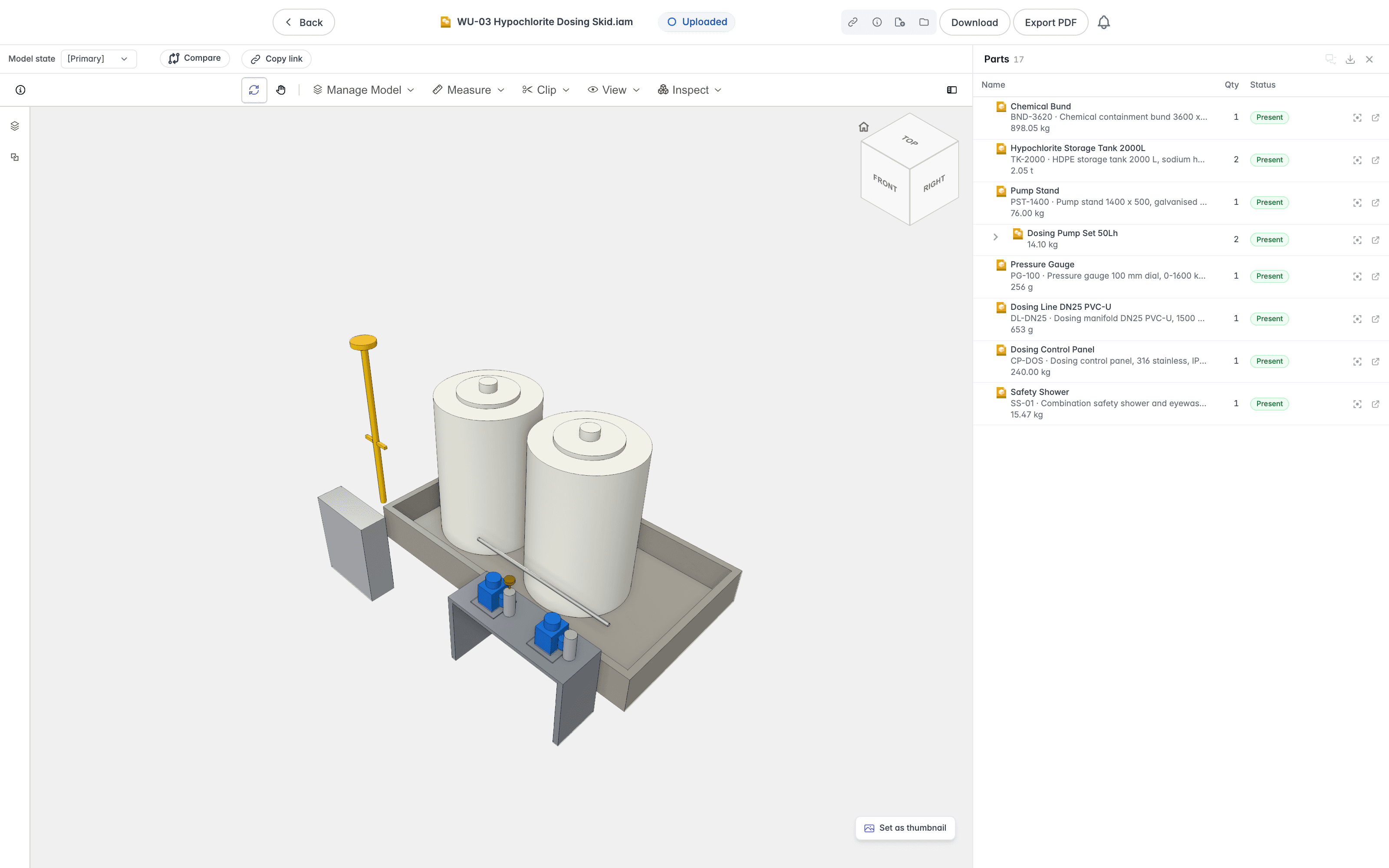
The panel title shows how many parts the assembly holds, counting those inside sub-assemblies. Each part has a row showing its name, how many times the assembly uses it, its status, and its mass. Wider screens also show the part's document in its own column, and narrower ones put the mass under the name. A sub-assembly has an arrow to expand the parts inside it.
A part's status is one of Present, Missing, Newer revision, Skipped, Suppressed, or Not drawn.
Each row has two buttons at the end:
- Zoom to frames that part in the 3D view.
- Open opens the part's own document.
Select the cross at the top of the panel to hide it and give the model the full width. Select the Parts tab at the right edge to bring it back.
Selecting Parts
You can select an individual part in two ways:
- Click the part's row in the Parts panel.
- Double-click the part in the 3D model.
The selected part is highlighted in the model and its row is highlighted in the list. Double-clicking in the model also zooms to the part. The Model Browser and Item Inspector panels open beside the model, showing where the part sits in the assembly and its properties, such as its part number, description, material, and mass properties.
Inspecting a CAD Model
Inventor, SolidWorks, and STEP models have an extra Inspect ribbon, beside View, for looking inside a model. It has up to four groups:
- Section cuts through the model. Choose X, Y, or Z to cut along that axis, or Box, and choose Off to remove the cut. Where the cut passes through a solid part it is hatched, and a blue handle appears on the cutting plane. Flip is available while an X, Y, or Z cut is chosen. With Box, Fit resizes the box around the selection, or around the whole model if nothing is selected.
- Explode pulls the parts of an assembly apart so you can see each one. Choose Radial, X, Y, or Z for the direction, set the Amount, then select Explode. Reset puts the parts back together.
- Isolate has Isolate and Show all, plus Hide and Ghost, which choose whether the other parts are hidden or shown as a faint ghost when you isolate. Isolate needs selected parts, and Show all needs an active isolation.
- PMI appears only when the model carries product and manufacturing information, such as a STEP AP242 file. PMI shows or hides the annotations, and All or Facing filters them.
None of these change the document. The Views panel can save the section and explode you have set up, covered in Saved Views.
Exporting the Bill of Materials
Select the download icon at the top of the Parts panel to export the assembly's bill of materials. Its tooltip reads "Export the bill of materials". A small menu offers two formats:
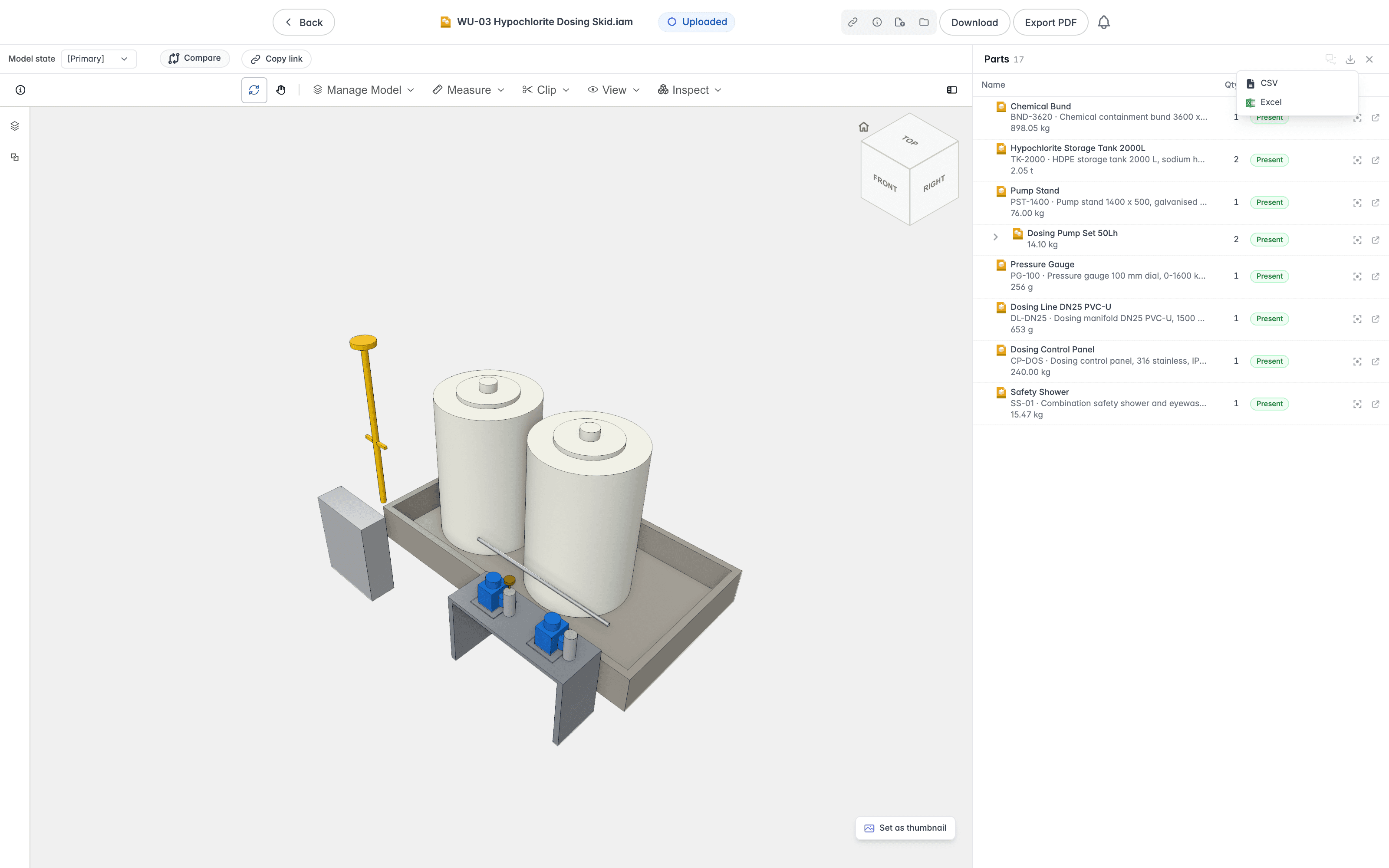
- CSV saves a comma-separated file that opens in any spreadsheet application.
- Excel saves a workbook with a single sheet named Bill of materials.
Your browser may ask where to save the file. It is named after the assembly, for example "WU-03 Hypochlorite Dosing Skid BOM.csv".
For the assembly's stored model, both formats hold the same table, with one row for each part or sub-assembly and these columns:
| Column | What it holds |
|---|---|
| Name | The part's file name. |
| Kind | Whether the row is a part or an assembly. |
| Part number | The part number from the CAD file. |
| Description | The description from the CAD file. |
| Material | The material, such as Generic. |
| Revision | The revision of the part the assembly is linked to. |
| Quantity | How many times the assembly uses the part. |
| Mass | The mass of one part. |
| Total mass | The mass of all the uses of the part together. |
| State | The part's status, such as Present. |
| Part document id | The identifier of the part's document in Lunr. |
The rows are listed in name order and are not nested, so a sub-assembly's parts are listed in the same table as the rest. A part used by a sub-assembly is counted across all the uses of that sub-assembly.
The Excel option is only available for the assembly's stored model. If you have switched to a model state or configuration, export as CSV. That file lists the parts in tree order, with the sub-assembly parts indented under their parent, and the columns Level, Name, Quantity, Part number, Description, Material, Status, Document, and Revision. It has no mass columns.
Raising an Issue on a Part
To raise an issue against a part, select the part, as described in Selecting Parts, then select Raise issue on selection, the speech bubble icon at the top of the Parts panel. The button appears only where your organisation uses coordination issues. While nothing is selected, or the selected part is not in the model, the button is unavailable, and its tooltip reads "Select a part in the list or the model to raise an issue on it."
The Raise an issue dialog opens with a picture of the view you are looking at, so the issue records what you saw.
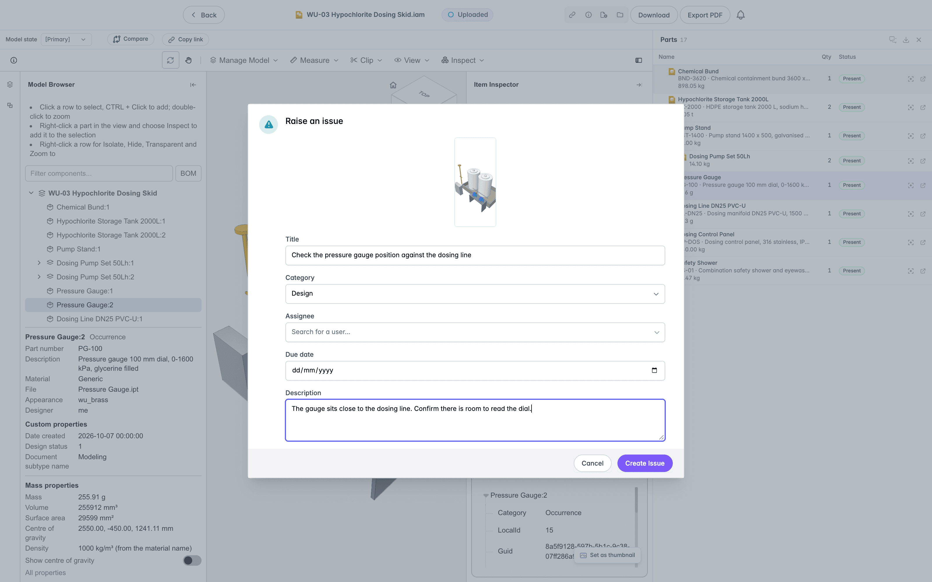
Complete the form:
- Title is required, up to 255 characters. Create Issue is unavailable until the issue has a title.
- Category lists your organisation's issue categories, and starts on the default one.
- Assignee is the person who picks the issue up. Search for a user to choose one, or leave it blank.
- Due date is optional.
- Description holds any detail that will help whoever picks the issue up.
Select Create Issue. A message reads "Issue raised" and gives the new issue's number, for example "ISS-CWU-2026-031-1 has been created." The issue belongs to the project that holds the assembly.
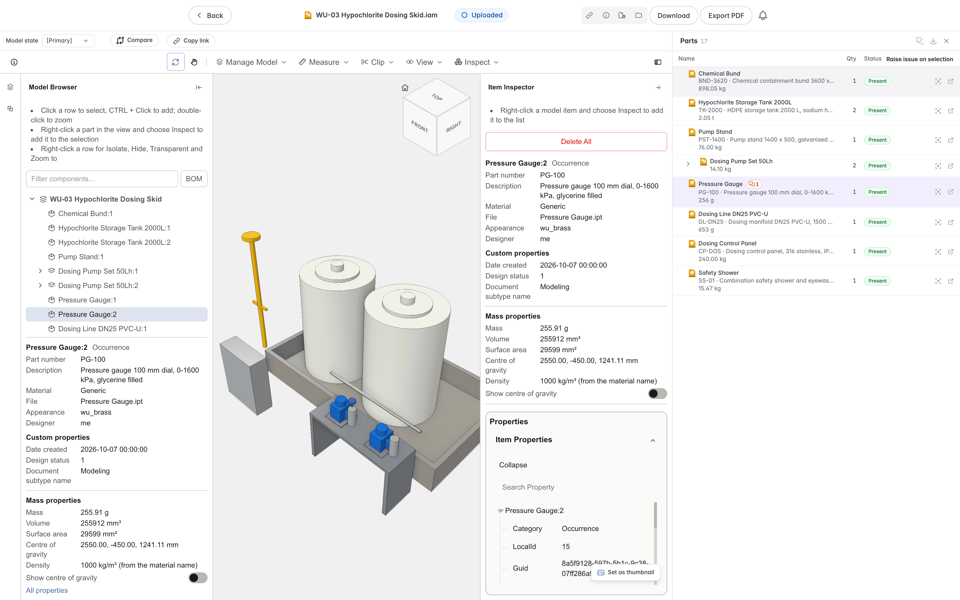
The part now shows a small issue badge beside its name, with the number of issues raised on it. Select the badge to open the issue. Where a part has several issues, the badge lists them so you can choose one.
An issue opens on its own page, showing its title, status, description, and the view it was raised on, with the category, assignee, and due date alongside. Select Take me there to return to the viewer at that view, with the part selected. See My Issues for the issue page, My Issues, and a project's Issues tab.
Model States and Configurations
Some CAD files hold more than one version of the same model: Inventor files have model states, and SolidWorks files have configurations. Where a file has them, a selector at the left of the toolbar lists them. It is labelled Model state, Configuration, or Model state / configuration, depending on what the file holds, and the model the viewer opens first is listed as [Primary].
Choose an entry to show the model in that state. The selector reads "Loading" followed by the name while the state is fetched, or "Building" followed by the name if it has to be built first. A state that is still being built reports "The model is still being built. Try again shortly.", and a failure offers Try again.
Comparing Revisions
Select Compare on the toolbar to compare the assembly you are viewing with another revision of the same document. The Compare revisions panel opens, with a Compare this revision with list of the document's other revisions, such as Revision 2. A document with only one revision reads "This document has no other revision to compare."
Choose a revision and the panel reports "Comparing the revision" while it works. It then lists the parts that differ, in up to four groups, each with a count:
- Added parts are in the revision you are viewing but not in the other.
- Removed parts are in the other revision but not in the one you are viewing.
- Moved parts are in both but sit in a different place in the assembly.
- Changed parts are in both but differ. Where the part's own revision changed, the row reads, for example, "Revision 1.0 to 1.1".
The other rows show the part's position in the assembly. A group with more than 200 parts lists the first 200, and Show all followed by the count lists the rest. Below the groups, the panel shows how many parts are unchanged. If nothing differs, it reads "No parts were added, removed, moved or changed", followed by the unchanged count.
In the viewer, each group has its own colour, repeated in a legend, and the unchanged parts are ghosted so the differences stand out. Select a row to frame that part in the 3D view. A part that the model does not draw reads "This part is not drawn in the model." The other revision is loaded into the viewer as Revision followed by its number and "(compared)", which is how its removed parts are shown. If that revision has no 3D model yet, its removed parts are listed but not drawn.
Select Clear the comparison to remove the colouring and the other revision from the viewer.
Viewing BIM Models
View and explore IFC, Navisworks, and Revit building models in Lunr's browser-based 3D viewer, with tools for navigation, measurement, sectioning, model inspection, clash detection, and scene management.
Viewing Point Clouds
View and analyse LAS and LAZ point clouds in Lunr's browser-based point cloud viewer, with tools for navigation, measurement, clipping, visualisation, saved viewpoints, and scene management.